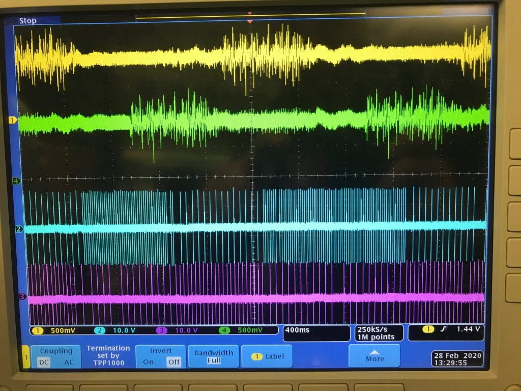
The blue and pink traces on the oscilloscope represents two of the many channels that are generating stimulation pulses, initially at 30Hz and 60Hz at different phase delays respectively. The green trace represents ADC recording that is wirelessly transmitted to a laptop running the closed-loop controller in real-time. Toggling the device’s analog recording sensor, the closed-loop controller on the laptop detects the change and modulates the stimulation protocols, communicating this back to the SoC chip wirelessly. The last portion of the video shows the new stimulation patterns of the blue and pink traces, at 30Hz and 20Hz, and phase delays respectively. In summary, we have demonstrated our system’s capability to simultaneously perform real-time recording and stimulation. Accordingly, it is feasible to implement closed-loop operations using our implantable system. A sophisticated controller is under development.